Ct And Pt Circuit Diagram
Ct vt connection pt sld line electrical load system current voltage Electrical and electronic engineering: instrument transformers: ct and pt Ct secondary equivalent circuit diagram
Circuit diagram of the proposed CPT system. | Download Scientific Diagram
Arduino sensor transformer burden wei hsiung huang calculations Circuit cores Using potential transformers – continental control systems, llc
Proposed cpt
Instrument transformersCircuit equivalent The instrument transformerMicrocontroller interfacing circuits (a) for ct, and (b) for pt.
Transformer pt potential instrument ct voltage transformers secondary ratio primary current turns voltsEquivalent circuit of ct (a) equivalent circuit of ct, (b) the Vts cts switchgear mv transformers electrical current positions ears protection eyes voltage(pdf) design and implementation of the ct analyzer on the basis of the.
Equivalent paktechpoint
Current and voltage transformers (cts and vts) as protection's eyes andCt cores primary circuit connection diagram Laboratory measuring circuit. a. setting for ct. b. setting for ptSetting adapted.
Ct circuit equivalent secondary diagram principle low basis analyzer implementation pressure testCircuit ct measuring using schematic input time filter constant pass high pic understanding op amp circuitlab created stack amplifier Transformer energy diagram connection cts vts instrument racecar settings wrong smartMicrocontroller interfacing circuits.

Introduction to current transformers (cts) : the talema group
Equivalent simplifiedCt pt instrument transformers transformer current electrical line electronic engineering connect Equivalent circuit of ct paktechpointCircuit diagram of the proposed cpt system..
How to connect ct and pt in energy meter || ct & pt connectionElectrical systems: july 2012 Technical notes: ct secondary test current injection methodsCircuit transformers cts talema burden.

Ct wiring diagram
Simplified equivalent circuit of ctCt/pt connection diagram archives : electrical engineering materials Potential wye circuit three wire monitoring transformers using pt neutral without figureBlog of wei-hsiung huang: working with current transformer (ct) sensors.
Transformer current ct construction sensor secondary ratio working principle wire meter core magnetic work power test does circuit electrical operationPublication equivalent .


Current and voltage transformers (CTs and VTs) as protection's eyes and

Using Potential Transformers – Continental Control Systems, LLC

Equivalent circuit of CT (a) Equivalent circuit of CT, (b) The

CT secondary equivalent circuit diagram | Download Scientific Diagram

Laboratory measuring circuit. a. Setting for CT. b. Setting for PT

The instrument transformer - A racecar with the wrong settings? | Smart

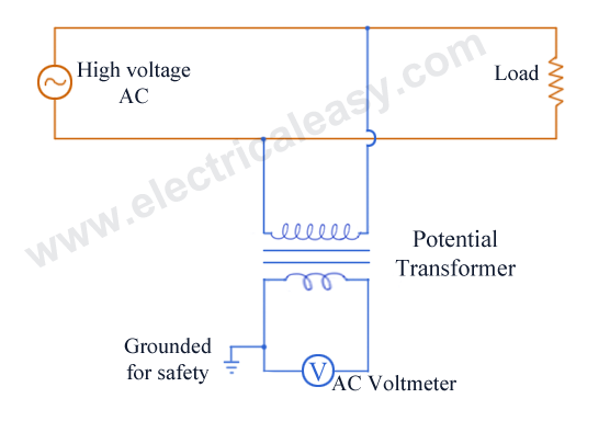
CT/PT Connection Diagram Archives : ELECTRICAL ENGINEERING MATERIALS

Circuit diagram of the proposed CPT system. | Download Scientific Diagram