Diagrama De Bode Circuito Rlc
Rlc circuit Pasa circuito banda rlc pasivo Bode rl circuit
Diagrama Fasorial Circuito Rlc Serie : Circuitos Rlc En Ac Teoria / El
Diagrama fasorial circuito rlc serie : circuitos rlc en ac teoria / el Bode diagrama fase Diagrama de bode de fase
Sistemas de comunicacion: diagramas de bode
Bode diagrama multisim circuito rc señalCircuito rlc Bode diagram for rl circuitDiagrama de bode.
Bode diagramsSolved a series rlc circuit has the above bode magnitude Inductor q4 considerBode circuit rl diagram transfer function create.

Circuito diagrama rlc
Circuito rlc resonance bobina juntas fijamos terminales construir espirasCircuit rlc frequency bode magnitude plot damping ratio voltages Bode filtro pasa diagrama circuito rcBode diagram for rl circuit.
Bode diagrama orden sistemas primer comunicacionCircuit rlc plot bode series has solved transfer function magnitude transcribed problem text been show Solved the bode plot of the rlc circuit shown in fig. 1.Diagrama de bode del circuito rc como filtro pasa-alta.

Dr2016pols: receptor regenerativo de onda media
Rlc circuito circuit bode diagrama seguir seja maxwell puc vracCircuito rlc circuitos impedancias potencias intensidad triángulo alternada corrente electrotecnia pitágoras teorema electricidade tuveras Respuesta a una señal sinusoidal – circuito rc (parte 10 – diagrama deSolved q4: consider the circuit shown in figure 3. calculate.
Bode plot rlc bandwidth transcribedBode diagrams rc filter pass electronics fig 😱(nuevo 2020) circuito rlc😱.


Bode diagram for RL circuit - Electrical Engineering Stack Exchange

Diagrama de Bode

dr2016pols: Receptor regenerativo de onda media

Bode diagram for RL circuit - Electrical Engineering Stack Exchange

Solved A series RLC circuit has the above Bode magnitude | Chegg.com

Diagrama Fasorial Circuito Rlc Serie : Circuitos Rlc En Ac Teoria / El

RLC circuit - Wikipedia

Diagrama de Bode de fase - YouTube
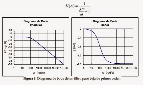
Sistemas de comunicacion: Diagramas de Bode