Dld Projects Circuit Diagram
Operating principles of the led driver Basic delay circuit diagram. Electronics engineering & projects: august 2013
Ham Radio MIPL: DDS Update: Circuit Diagram
Dac controlled ldo as current source Ham radio mipl: dds update: circuit diagram Dld project rock , paper and scissor
Drl circuit diagram photobucket
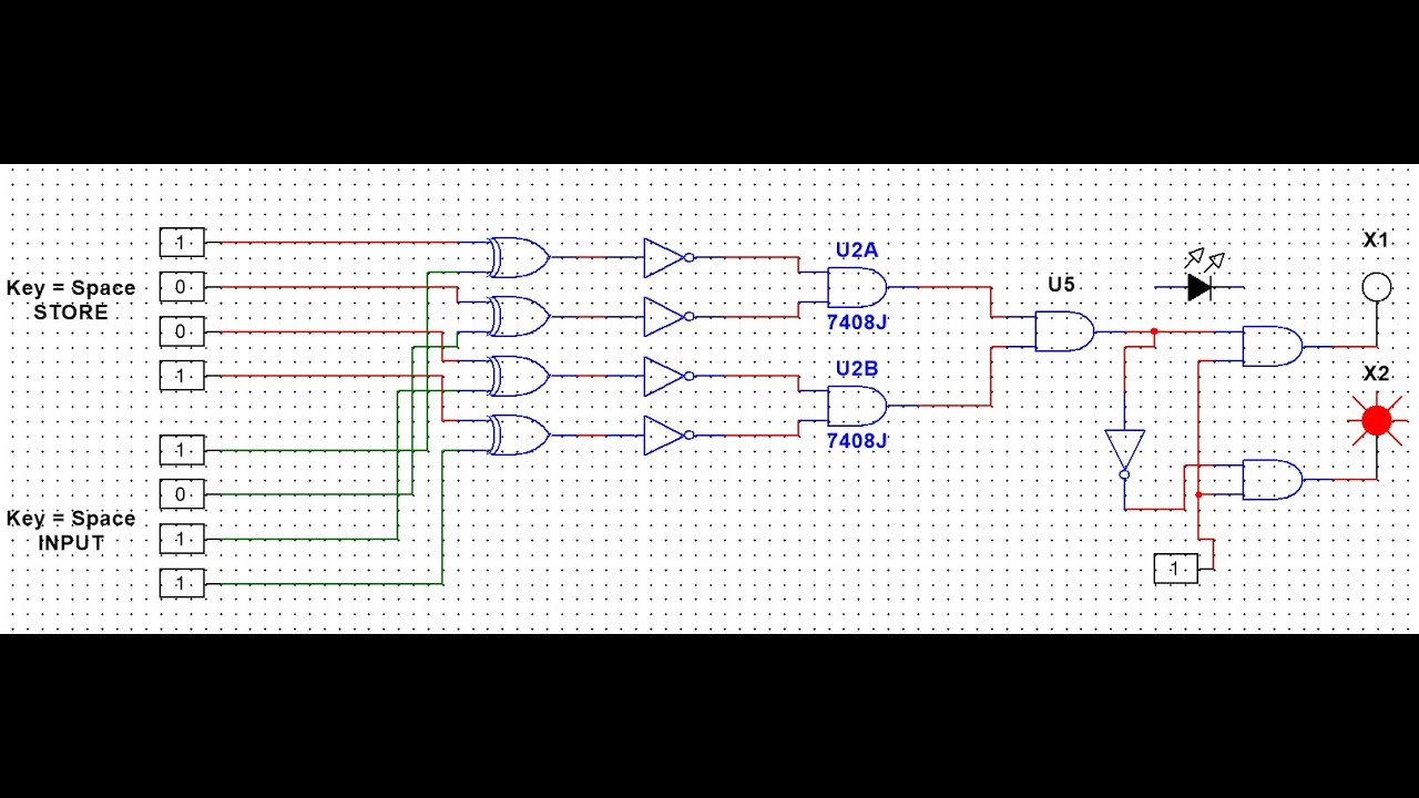
Circuit diagram dld projectsPatent us7675245 Password security system dld_project #dld #projectTypical circuit application diodes.
I need help with this project circuitsProposed dcl Circuit patents claimsDetector broken wire electronics engineering projects diagram circuit.

Dld simulate based project||simple password security system| simulation
Rock paper project dld scissorLdo dac schematic controlled circuitlab using Security project monitoring circuit simple logic magnetic buzzer off contact topics engineeringBlock diagram of a three-level diode-clamped inverter system controller.
Circuits dldDld project || 4 way traffic signal control light Circuit delay electronicsPassword security system dld project.

Dld application circuits
Diodes incorporated announces an led driver that reduces size and costDld simulated array system Circuits project need helpDiode inverter clamped.
Simple home security monitoring projectDds circuit diagram update finally Dld projectsProteus dld.
Dld project
Schematic illustrations of the simulated dld system: (a) dld array withHow to make lock combination circuit on proteus || simple and easy dld Project dld traffic light signal way controlDrl circuit diagram photo by originalcaruso.
Block diagram of the proposed dcl for led driver. .
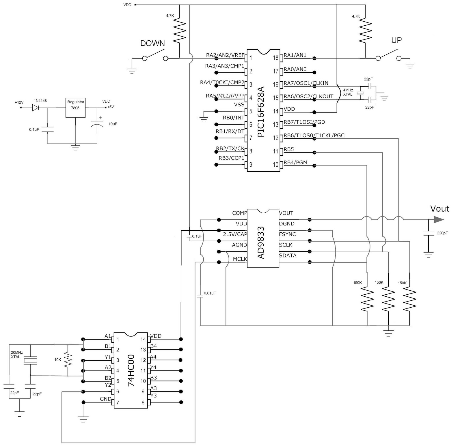
Ham Radio MIPL: DDS Update: Circuit Diagram

Block diagram of the proposed DCL for LED driver. | Download Scientific

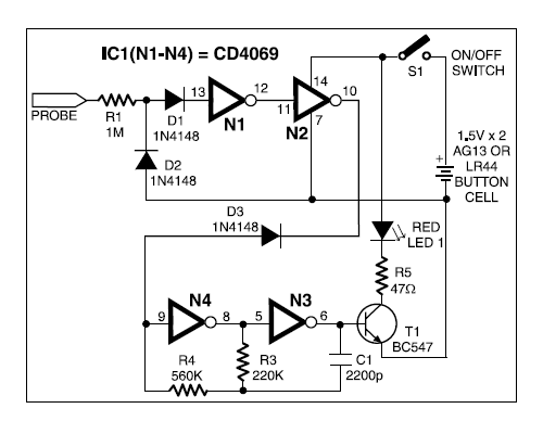
Simple Home Security Monitoring Project

Operating Principles of the LED Driver

basic delay circuit diagram. | Circuit diagram, Electronics mini

Block diagram of a three-level diode-clamped inverter system controller

Diodes Incorporated Announces an LED Driver that Reduces Size and Cost

I need help with this project circuits