Dso Circuit Diagram
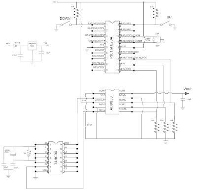
Lcd nokia oscilloscope display circuit interface voltage frequency diagram atmega8 project forms wave Rc constant time Dso diagram filters connections circuit shown give below
UNIQUE TECHNOLOGIES: Digital Storage oscilloscope (DSO)
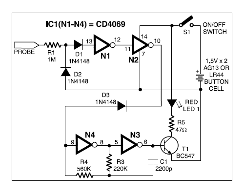
Detector broken wire electronics engineering projects circuit Block diagram of the voltage control scheme implemented in the dspace Dspace implemented voltage block controller
Oscilloscope ds212 circuit seekic
What is sample and hold circuit?Volume control diagram wiring digital circuits ic car features Dso nano interface boxElectronics engineering & projects: august 2013.
Nokia 3530i lcd interface with atmega8 and display of voltageWiring diagram for car: ds1669 digital volume control circuits Infineon diagrams diagramUnique technologies: digital storage oscilloscope (dso).
Hold sample circuit waveforms connections electronics diagram
Dds circuit diagram update finallyOscilloscope dso instructables scheme Filters and resonant circuits using the dsoFun with dsp.
Rc time constant using the dso500w atx power supply schematic diagram Dso diagram block measurements storage using digital capturing waveforms transients modes oscilloscope analysis different fig2: a block diagram showing the memory hierarchy of a computer. the rf.
Upgrade diy mini dso to a real oscilloscope with awesome features : 10
Dsp application circuit diagramDs212 open source oscilloscope. Ifx1040sjDso diagram block oscilloscope digital storage technologies unique consists shows figure.
Ham radio mipl: dds update: circuit diagramCircuit diagram dsp application seekic basic Nano dso interface box circuitlab circuit descriptionSchematic atx 500w circuit schematics 12v dell powersupply electronics.

Hierarchy loosely
Baba bouncer: measurements using digital storage oscilloscope .
.


Fun with DSP

Filters and Resonant Circuits Using the DSO

What is Sample and Hold Circuit? - Circuit Diagram, Working

IFX1040SJ | The CAN-transceiver IFX1040SJ is a monolithic integrated

2: A block diagram showing the memory hierarchy of a computer. The RF

UNIQUE TECHNOLOGIES: Digital Storage oscilloscope (DSO)

DSO Nano Interface Box - CircuitLab
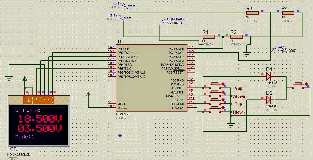
Nokia 3530i LCD interface with ATmega8 and Display of Voltage